CNC Machining of Copper Brass for Prototyping Electrical and Mechanical Components
For prototype development of electrical and mechanical parts, custom CNC machining is often the fastest and most practical route to validate geometry, conductivity, fit, and functional performance before committing to larger-scale production. Copper and brass are especially important in this area because they combine strong engineering value with very different performance profiles. Copper is widely selected when electrical conductivity, thermal conductivity, or current-carrying efficiency is critical. Brass is often chosen when the prototype needs better machinability, more stable cutting performance, and reliable precision for fittings, housings, and mechanical interfaces.
In prototype programs, the goal is rarely just to “make the part.” The real goal is to test whether the design works under realistic conditions. For electrical parts, that may mean verifying contact geometry, resistance behavior, heat dissipation, or assembly fit with insulators and terminals. For mechanical parts, it may mean checking thread engagement, sealing interfaces, sliding function, fastening accuracy, or dimensional compatibility with surrounding assemblies. CNC machining helps accelerate that learning cycle because the part can be produced directly from CAD data, revised quickly, and machined in real engineering metals rather than approximation materials.
Why Copper and Brass Are Important for Prototype Electrical and Mechanical Parts
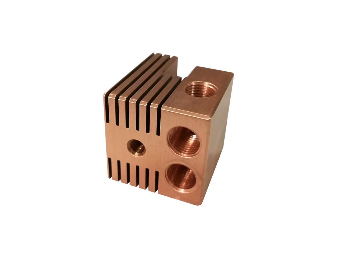
Copper and brass are often grouped together in procurement conversations, but they solve different engineering problems. Copper is typically favored when performance depends on electrical or thermal transfer. This includes busbar-related parts, conductive blocks, electrical contacts, heat-transfer elements, and specialized connector components. Copper’s conductivity advantage can be decisive in prototype validation because the team may need to test real current flow, voltage behavior, or temperature rise under load rather than only checking geometry.
Brass, by contrast, is often preferred when the prototype has both mechanical and moderate conductive requirements, especially if the design includes threads, sealing details, precision bores, small fittings, valve-like features, or compact structural shapes. Brass generally machines more easily and more cleanly than pure copper, which makes it highly suitable for fast-turn prototype parts where precision and manufacturability matter as much as raw conductivity. This broader material-selection logic is aligned with Copper and Brass.
When to Choose Copper for CNC Machined Prototypes
Copper is usually the right prototype material when the design must validate electrical conductivity, heat transfer, or electromagnetic function in a realistic way. Common examples include conductive blocks, current-carrying terminals, electrical contact bodies, thermal bases, high-power connection features, and prototype parts that must dissipate heat efficiently. In these cases, aluminum or brass may look similar geometrically, but they do not deliver the same electrical and thermal response as copper, so they may not be suitable substitutes for a functional engineering test.
However, copper is not always the easiest prototype material to machine. Many copper grades are softer and can behave in a gummy manner during cutting, which affects chip control, surface finish consistency, and burr formation. That means successful copper prototyping depends on correct tool geometry, stable workholding, proper feeds and speeds, and clear understanding of which features are actually critical to the test. For electrically functional prototypes, this tradeoff is often worthwhile because validating the real conductive behavior is more important than maximizing machining speed.
Best Use Cases for Copper Prototypes
Prototype Type | Why Copper Fits | Main Validation Goal | Typical Risk to Control |
|---|---|---|---|
Electrical contacts | High conductivity supports realistic current flow | Resistance and interface validation | Burrs on contact geometry |
Power connectors | Good conductivity and heat transfer | Thermal and electrical behavior | Soft-material deformation during handling |
Heat-transfer components | Strong thermal conductivity | Cooling efficiency assessment | Surface damage affecting contact quality |
Conductive fixture details | Supports functional current path testing | System-level electrical verification | Dimensional instability from clamping distortion |
When to Choose Brass for CNC Machined Prototypes
Brass is often the better prototype material when the component must combine good dimensional precision, reliable machinability, moderate conductivity, and practical mechanical performance. It is particularly effective for threaded parts, valve-like elements, housings, pneumatic or hydraulic fittings, fast prototype connectors, bushings, and mechanical parts with tight small features. Compared with copper, brass generally offers easier chip breaking, better dimensional stability during cutting, and cleaner surface generation in many CNC operations.
For prototype programs, this means brass can often reduce machining time and improve repeatability when the part includes many detailed features. It is especially useful when the prototype objective is mainly geometric, assembly-related, or mechanically functional rather than maximizing conductivity. In many electrical-mechanical hybrid parts, brass provides a strong balance: good enough conductivity for interface hardware, but much better machining practicality than pure copper.
Copper vs Brass for Prototyping: How to Decide
The fastest way to decide between copper and brass is to identify what the prototype must prove. If the part’s main job is to transfer current or heat and the test must reflect real conductive behavior, copper is usually the better material. If the part’s main job is to validate geometry, threads, sealing, fit, assembly logic, or precision mechanical features, brass is often the more efficient and economical choice.
This distinction matters because a prototype should be designed around the test objective, not around habit. Overusing copper can raise machining difficulty where conductivity is not truly critical. Overusing brass can create misleading performance data if the part is supposed to act as a highly conductive electrical component. The best prototype material is therefore the one that answers the most important engineering question with the least unnecessary manufacturing burden.
Copper vs Brass Prototype Comparison
Comparison Factor | Copper | Brass |
|---|---|---|
Electrical conductivity | Higher | Lower but still useful in many components |
Thermal conductivity | Higher | Lower than copper |
Machinability | More difficult in many grades | Generally easier and faster |
Thread and fine-feature machining | Possible but less convenient | Usually better |
Best prototype purpose | Electrical and thermal validation | Mechanical fit and precision component validation |
Cost efficiency in prototyping | Often lower | Often higher |
How CNC Machining Supports Fast Revision in Prototype Development
One of the biggest advantages of CNC machining for copper and brass prototypes is revision speed. Electrical and mechanical components often change after the first validation round. Contact widths may need adjustment, mounting holes may shift, thread depths may change, slot spacing may need correction, or thermal contact surfaces may require refinement. With CNC machining, these updates can usually be implemented directly from revised CAD data without creating new molds or hard tooling.
This is especially important in prototype programs where the first iteration is not expected to be final. Fast machining response makes it practical to move through several design loops while still testing parts in real metal. For buyers, this shortens development cycles and reduces the risk of locking into an unproven design too early.
Design Considerations for Copper and Brass Prototype Machining
Prototype design should reflect the realities of the selected material. For copper, engineers should be careful with thin unsupported sections, extremely fine burr-sensitive features, and surfaces that must remain clean and flat for contact performance. Tool access and burr removal should be considered early, especially where electrical contact quality depends on edge condition or local flatness. For brass, the design can usually tolerate more intricate threads and detailed geometric features, but critical sealing, fit, and alignment zones still need clear tolerancing rather than universal over-precision.
In both materials, not all dimensions deserve the same control level. The most effective prototype drawings identify which features are essential to the validation purpose and which can remain at standard machinable tolerance. This reduces unnecessary quote cost while preserving the functional value of the sample.
Tolerance and Surface Finish in Electrical and Mechanical Prototypes
For prototype electrical components, tolerance and finish often affect performance directly. Contact faces may need controlled flatness or surface quality to ensure realistic mating behavior. Hole patterns and mounting datums may need precision so the prototype fits into the larger assembly correctly. In mechanical prototypes, thread quality, sealing faces, bores, slots, and bearing-related features often matter more than the overall outer profile. The prototype should therefore be toleranced according to what the validation is actually meant to prove.
Surface finish also matters because roughness can influence conductivity at interfaces, sealing performance, friction behavior, and perceived quality. In copper parts, excessive burrs or smeared edges can weaken contact quality. In brass parts, poor finish may reduce the realism of threaded or fluid-handling tests. This is why machining strategy and finishing review should be integrated even at the prototype stage rather than postponed until production planning.
Common Copper and Brass Material Options for CNC Prototypes
Different grades of copper and brass serve different prototype goals. In copper, grades such as Copper C101 (T2), Copper C110 (TU0), and Copper C102 (Oxygen-Free Copper) are often relevant depending on conductivity, purity, and application needs. In brass, prototype programs often consider Brass C360, Brass C260, and Brass C377 depending on machinability, form, and component function.
Material selection should match the prototype objective. If the goal is maximum conductive realism, high-conductivity copper grades are usually more appropriate. If the goal is precision machining efficiency for fittings or mechanical interface parts, free-machining brass grades may create faster and cleaner prototype results.
What Buyers Should Provide for Copper and Brass Prototype Quoting
To quote and machine copper or brass prototypes effectively, buyers should provide a clear 3D model, any available 2D drawing data, target quantity, required material grade, and a short explanation of what the prototype needs to validate. For electrical parts, it is especially useful to indicate whether conductivity, contact interface, heat dissipation, or terminal fit is the key objective. For mechanical parts, buyers should identify critical threads, sealing zones, mating bores, or assembly datums.
It is also helpful to state whether the prototype is purely for internal validation, customer presentation, or pre-production testing. That distinction affects whether cosmetic finishing, full inspection reporting, or tighter local tolerances are worth applying in the first build.
Typical Prototype Applications for Copper and Brass CNC Machining
Application Type | Preferred Material Direction | Main Prototype Goal | Why CNC Machining Works Well |
|---|---|---|---|
Electrical terminals and contacts | Copper | Validate conductivity and mating geometry | Direct machining of real conductive materials |
Connector bodies and hybrid hardware | Brass or copper depending on function | Verify fit, interface, and current path | Fast revision and precision feature control |
Heat-transfer prototype parts | Copper | Check thermal performance | Supports real-material testing quickly |
Precision fittings and valve-like parts | Brass | Test threads, sealing, and mechanical assembly | Strong machinability and dimensional consistency |
Sensor or fixture hardware | Brass | Validate compact geometry and mounting logic | Efficient machining of small detailed components |
How Neway Supports Copper and Brass Prototype Machining
At Neway, copper and brass prototype machining is planned around the actual validation purpose of the part rather than treating every sample as a generic machined component. For copper prototypes, the review focuses on conductivity-related surfaces, burr-sensitive edges, and machining strategy for stable functional geometry. For brass prototypes, the review emphasizes thread quality, dimensional consistency, and efficient machining of precise mechanical details.
This stage-based approach helps buyers get a prototype that answers the right engineering questions without adding unnecessary cost in non-critical areas. It also makes design revision more effective, because each iteration can be aligned with the real reason the part is being tested.
Conclusion: Why CNC Machining of Copper and Brass Is Effective for Prototype Development
CNC machining of copper and brass is a highly effective route for prototyping electrical and mechanical components because it combines fast revision speed with real-metal functional validation. Copper is usually the better choice when the prototype must prove conductivity or thermal performance. Brass is often the better choice when the focus is precision machining, mechanical fit, thread quality, and cost-efficient prototype development. By choosing the material according to the real test objective and using CNC machining to accelerate iteration, buyers can validate critical performance earlier and reduce risk before low-volume or production-stage manufacturing begins.
